

![]()
OVERVIEW
Radio access networks of multiple communication service providers (CSP) often provide coverage to the same areas. With user traffic constantly changing throughout the day, the network coverage sometimes needs to be more varied between CSPs. TM Forum’s Catalyst “AI-powered cooperation for efficient networks” program is aimed to provide self-design and intelligent networking between Radio-Access Network (RAN) and other network elements with overlapping CSP coverage to cut costs, boost efficiency, and help operators become green by reducing their carbon footprint.
THE GOAL
The goal was to develop a framework that would utilize BSS and OSS components to autonomously manage and reconfigure networks in real-time for all the CSPs involved in this process without stopping or interrupting other business operations. Other objectives were minimization of energy consumption and maximization of energy efficiency among different mobile network operators (MNOs).
The NATEC team combined forces with Vodafone and Orange that were looking to solve the challenge of automatic negotiations between CSPs in order to decide on a single operator to provide coverage in an area with temporary low busy hours slots and to automatically reconfigure the networks of all CSPs accordingly, thus aiming to reduce individual (per-CSP) and collective energy consumption and maximize utilization of green energy.
THE TEAM
- Vodafone and Orange. Project champions and technical leads that provided guidance to ensure the alignment of the overall project and created realistic network scenarios to closely mirror real-world networks in terms of architecture and parameters.
- Comarch. Responsible for driving the end-to-end sequence of project scenarios, preparing tests, and providing the necessary OSS and AI systems and components for project execution.
- NATEC. The task was to provide the Enterprise Integration component and Process Flow Management API that are fully compliant with TM Forum’s Open Digital Architecture in order to combine existing systems together and interconnect system components in a proper way, and also to provide all the required guidance, maintenance, and support to ensure operationability.
To streamline development processes, enhance the agility of existing systems, and make all the assets and components controllable, we utilized our MEF.DEV platform and its BPMN + Low-Code capabilities. The platform also served as a place to put the functionalities that don’t fit well in other components, such as management GUIs, extra control loop logic, and transformations between both standard and non-standard APIs, among other tasks aimed at simplifying integration. - Inetum. Focused on implementing the On Guard Tour algorithm, which determines the CSPs responsible for managing the RAN. They also handled the integration logic in alignment with TM Forum assets.
THE CHALLENGE
From a technical perspective, the primary challenge lies in establishing a dependable automated framework for facilitating communication among CSPs, allowing them to synchronize their responsibilities for area coverage and ensure the consistent service of subscribers. These responsibilities serve as triggers for a fully automated network redesign, involving actions such as toggling RAN-managed entities on and off, adapting the core network to the altered RAN topology, and adjusting connectivity, all while continuously optimizing network design and efficiently allocating resources based on strategic goals represented by multiple optimization criteria. In operational terms, the primary challenge involved the efficient reconfiguration of the network to conform to the mutually agreed-upon area coverage and division of responsibilities, while also adhering to the policies of individual CSPs. On a commercial front, the central obstacle revolved around maintaining uniform inter-CSP accounting and billing procedures. This ensures that the area coverage responsibility split remains commercially advantageous for all participants and remains in compliance with regulatory requirements.
THE SOLUTION
The strategy was to reduce energy consumption by selectively deactivating RAN components, either entirely or partially, during periods of reduced demand. This approach results in significant energy savings. Furthermore, it encompasses a comprehensive network overhaul that not only involves the RAN but also the 5G core infrastructure. This reconfiguration adapts to the new requirements set by strategic intents that determine when and where the RAN should be active or inactive.
The proposed solution is based on using a variety of systems and components, including software that integrates, controls, and manipulates all the available data and reports on the obtained result.
SYSTEM COMPONENTS
- On-Guard Tour. A decision-making algorithm divides the responsibilities for covering certain RAN areas between operators to maximize energy efficiency.
- Enterprise Integration layer provided by MEF.DEV.
- OSS Web Console. Controlling element that presents a unified view of the network in various forms and provides information regarding the condition of the network, its control mechanisms, and service operations.
- Resource Catalog. The main repository for information models, templates, and asset orchestration.
- E2E Orchestrator. Translates intents for the network into a set of operations.
- Performance Management. Provides predicted demand for the coverage area along with information about the current energy consumption, via KPIs.
- Dynamic Resource Inventory. Represents the network of each CSP based on raw information from various sources.
- MIRA. AI-powered decision-making algorithm that is responsible for designing the network and resource allocation.
- Kafka and Nifi. Integration tools for event-driven cooperation between architecture components.
THE WORKFLOW
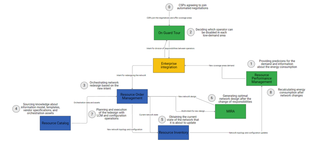
As illustrated in the diagram above, the workflow comprises the following steps:
Step 0: Two or more CSPs enter into a cooperative agreement, in compliance with the National Regulator Act, to share responsibilities for delivering services to each other’s customers in agreed-upon geographical areas during periods of low demand. This step serves as a prerequisite for the use case.
Step 1: Operators provide their demand expectations for each coverage area, including estimated active user equipment sessions and bandwidth. The Enterprise Integration module selects areas with low demand for On-Guard Tour (OGT) negotiations based on a predefined threshold. Additionally, it provides the current energy consumption data for these areas and the savings achieved so far.
Step 2: The OGT module determines the division of responsibilities for the low-demand areas by designating one of the operators as “on guard.” Other operators cease providing RAN coverage in areas where they do not hold this role.
Step 3: The new division of responsibilities is conveyed to the Resource Order Management (ROM) as an intent change. This specifies which areas should be enabled or disabled for a given operator in the upcoming period, along with the global optimization goals, with a focus on energy efficiency. The orchestrator’s responsibility is to update the network accordingly by enabling/disabling RAN elements (e.g., cells and gNodeBs) and reconfiguring the transport and core network to align with the altered RAN coverage requirements.
Step 4: ROM contacts the Resource Catalog to obtain essential information, including the orchestration template, network element/xNF specifications, and an information model describing the network entities involved. It also loads the corresponding orchestration artifacts.
Step 5: ROM retrieves the current state of the network from the Resource Inventory, encompassing the network’s topology (from low-level infrastructure to logical topology and slices) and the current configuration of network elements, including administrative and operational states of cells and gNBs. It combines this information to generate a new configuration and network topology that reflects the updated intent. This results in an intermediate, sub-optimal network design.
Step 6: The design and global intents, including optimization objectives, are forwarded to MIRA, responsible for determining how to implement them in the network. MIRA combines the design with available infrastructure, resource usage and efficiency data, technological constraints, and optimization intents to produce a comprehensive design, including deployment and routing plans for all elements in the input topology.
Step 7: ROM prepares a multiphase orchestration plan for implementing the final network design. It identifies necessary operations on managed entities, determines their order, and prepares reusable orchestration building blocks and assets. ROM executes the end-to-end orchestration scenario and updates the resource inventory accordingly.
Step 8: Resource Performance Management continuously monitors changes in topologies and configurations, enabling adaptation to the new situation with energy consumption calculations and other KPIs.
The process then repeats, with new demand predictions for the next period provided by Performance Management, initiating the next iteration of the closed-loop. Upon completion of calculations, information about energy consumption and updated demand values are accessible to Enterprise Integration for further processing.
THE NATEC TEAM CONTRIBUTION
The MEF.DEV platform has made a significant contribution to the success of the Catalyst project by providing essential capabilities for the project’s goals and objectives.
1. Enterprise Integration capabilities ensured seamless communication and data exchange between multiple network systems and their components, thus bringing network orchestration to a new level, ensuring efficient communication and data exchange between different parts of the network.
2. Process Flow Management API helped manage the flow of data, ensuring that each step in the workflow was executed smoothly and efficiently. It contributed to the automation and orchestration of processes, reducing the need for manual intervention.
3. The MEF.DEV platform’s BPMN combined with Low-Code capabilities streamlined the development processes within the project. It enhanced the agility of existing systems, making them more responsive to changing network conditions. This flexibility allowed for the rapid development and deployment of network services and applications, improving the overall efficiency of the project.
4. Without having any predefined technical requirements, the MEF.DEV platform became a sort of collaboration hub for all the involved teams of developers and provided them with a clear, logical, and understandable way of collaboration to efficiently interconnect system components and ensure they work together smoothly by using the BPMN + Low-Code approach. Consequently, it helped to develop, test, and deploy all the required network services and the involved business logic processes and adapt them to constantly changing network requirements on the fly.